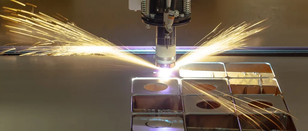
What is plasma cutting?
You’ve no doubt seen the lightning that cuts through the night sky during a thunderstorm – this naturally high-temperature arc of more than 30,000 degrees Celsius is the inspiration for plasma cutting technology.
Engineers have discovered that when compressed air passes through a high-voltage arc, gas molecules are “torn” into charged particles, forming the fourth state of matter – plasma. This is an ultra-high-temperature jet, which can instantly melt the metal, with a high-speed airflow to blow away the slag, to achieve precise cutting.
In our sheet metal processing workshop, a standard plasma cutting machine takes only 2 seconds to penetrate a 20mm thick steel plate, and the error is no more than 0.5mm, the efficiency is 3 times of the traditional oxyacetylene cutting.

The Birth of Plasma Cutting
In 1957, Robert Gage, an engineer at Union Carbide in the United States, found that traditional acetylene cutting could not handle the new titanium alloy when developing missile casings. He stumbled upon an incredible stable jet stream when the arc encountered argon, from which plasma cutting technology entered a period of rapid development.
Key Development Nodes:
- 1962: The first water-cooled plasma cutting machine was introduced (cutting thickness exceeded 50mm).
- 1983: Application of high-frequency inverter power supply technology (40% reduction in energy consumption)
- 2008: Fine plasma cutting system launched (kerf accuracy of ±0.1mm)
Principle of Plasma Cutting
Key Steps
- Arc ignition: guided arc between tungsten electrode and nozzle (approx. 100 A current)
- Gas ionization: compressed air (or nitrogen/oxygen) is heated above 15,000°C and electrons detach from the nucleus to form a plasma.
- Energy focusing: Plasma beam diameter is controlled at 1-3mm by vortex ring technology, energy density reaches 10^6 W/cm².
The process is similar to “spraying lava with a high-pressure water gun” – it maintains high temperatures and packs a punch.
Three Core Components
Power System
The power module with IGBT inverter technology can dynamically adjust 200-400A current within 0.01 seconds. Ensure stable cutting from 0.5 mm-thick plate to 150 mm-thick plate.
Electric Arc Generator
The built-in oscillator generates a 30,000Hz high-frequency current, increasing gas ionization efficiency by 5 times. The latest model adopts double eddy current technology, the arc compression degree is 60% higher than the traditional equipment, which is equivalent to reducing the diameter of the spray gun from the mouth of a mineral water bottle to the thickness of a straw.
Gas Controls
The multi-stage gas mixing system can precisely control the ratio of argon, hydrogen and nitrogen. When cutting stainless steel, the gas mixture of 95% argon + 5% hydrogen can effectively prevent the oxidation of the kerf, and the surface finish can reach Ra3.2μm.
Why Plasma Cutting?
Here are 6 distinct advantages of plasma cutting technology:
- Speed: 8mm carbon steel cutting speed up to 3800mm/min (8 times that of flame cutting)
- Materials: All metals from aluminum, copper to titanium can be cut.
- Accuracy: beveling error <1° (>5° common in traditional processes)
- Cost: only $0.3 per meter cut (1/7th of laser cutting)
- Safe: no gas bottle required, fire risk reduced by 90
- Environmental protection: 65% reduction in dust emissions (when equipped with a dust removal system)
Handheld Plasma Cutting vs. Automation Plasma Cutting
| Typology | Handhold | ESAB PT-36 CNC |
| Cutting thickness | ≤50mm carbon steel | ≤150mm stainless steel |
| Movement accuracy | ±1.5mm | ±0.2mm |
| Typical scenario | Outdoor Plumbing Repair | Ship Deck Batch Lowering |
| Cost range | 1,500− 5,000 | 20,000− 200,000 |
| Representative models | Miller Spectrum 875 | ESAB PT-36 CNC |
Plasma Cutting vs Flame Cutting vs Laser Cutting
If you’re not sure what cutting method is appropriate for your material or usage scenario, take a look at the decision-making quick checklist I’ve put together for you:
| Scene Characteristics | Preferred Process | Key Rationale |
| Field work/thick carbon steel | flame cutting | Portable equipment and easy access to fuel |
| Thin Plate/High Precision Requirements | laser cutting | No beveling of the incision and minimal heat-affected zone |
| Mixed metals/medium plate | plasma cutting | Best overall price/performance ratio and adaptability |
Note: According to 2023 Metalworking Magazine research data, plasma cutting equipment purchases increased 23% year-over-year in the 6-30mm plate processing segment
Standard Operating Procedures for Plasma Cutting
The Three Principles of Security
- First you will need to wear an ANSI certified #5 level visor (strong UV protection)
- Maintain air circulation in the work area to avoid ozone concentrations exceeding 0.1 ppm
- Ground wire diameter ≥ 8mm, regular testing resistance value <4Ω
Debugging Plasma Cutting Machine
- Equipment check: confirm gas pressure (0.5-0.7 MPa), ground wire connection, wear of consumables (electrodes need to be replaced if dented > 2 mm)
- Parameter setting: Adjust the current and gas flow according to the material and its thickness. (Example: 10mm stainless steel → current 130A / gas flow 12L/min)
- Test cut verification: first find a piece of waste material for 5cm straight line cutting, check the color of the cut (silver white is good)
- Formal operation: keep the gun nozzle 3-5mm away from the workpiece and move at an even speed (novice users are advised to use the guide rail as an aid)
- Quality Inspection: Measurement of bevel angle using weld inspection ruler, filing to check slag hanging situation
Parameter Settings for Different Materials
Different materials need to be adjusted to the parameters of plasma cutting, otherwise it will not be able to achieve the best cutting quality, or even destroy the material, here we take some common metals as an example.
Aluminum:
- Plate thickness 5mm
- Cutting speed: 800mm/min
- Use of nitrogen + hydrogen gas mixture with a gas flow rate of 8 L/min (ratio 7:3)
- Current 30A, voltage 90V (to avoid excessive heat conduction leading to arc breakage)
- Adoption of the “perforate first, surround later” strategy to prevent splash clogging of the nozzle
Stainless steel:
- Plate thickness 3mm
- Cutting speed: 500mm/min
- Oxygen is used for cutting (to improve the finish of the cut), with a gas flow rate of 10L/min.
- Current 40A, Voltage 120V
- Add 10° backward tilt (reduces bottom slagging)
Carbon steel plate
- Plate thickness 8mm
- Cutting speed: 300mm/min
- Cutting gas selection of oxygen, gas flow rate of 12L / min
- Current 60A, Voltage 150V
Solutions to High-Frequency Problems
Problem: Wave pattern on cut surface
- Cause: Unstable cutting speed/high gas water content
- Countermeasures: Use of automatic traveling racks/addition of refrigerated dryers
Problem: Serious slag hanging on the bottom
- Causes: Insufficient gas pressure/too fast cutting speeds
- Countermeasure: Increase air pressure by 0.02MPa for every 1mm of thickness.
Problem: Incision is wide at the top and narrow at the bottom
- Cause: High muzzle height/low current parameter
- Countermeasure: Install height sensor / adjust according to the formula: current (A) = plate thickness (mm) × 10 + 20
Problem: Frequent arc breaks
- Cause: Poor grounding/electrode loss
- Countermeasure: Regularly use vernier calipers to detect the electrode depression and replace it immediately if it exceeds 1.5mm.
Problem: Abnormal consumption of electrodes
- Cause: Excessive arcing time/cooling system failure
- Countermeasures: Setting 2 seconds automatic arc break protection/cleaning water-cooled pipeline
Actual Case: Sheet metal factory cutting 10mm aluminum plate appeared wave pattern, eventually found that the compressed air contains too much water, add the three-stage filter after the problem disappeared.
Does Your Metalworking Need An Upgrade?
If you are hesitating to upgrade your metalworking equipment, you can do the math with the costing formula we have put together. Of course, cost is only one of the factors, upgrading to new equipment can increase your competitiveness in the industry and can help you get more orders.
Costing Formula:
Payback cycle (months) = (equipment price – residual value of old equipment) / (average monthly incremental revenue + labor savings – consumable costs)
EXAMPLE: A machine shop purchased an $800,000 plasma cutting system:
- Residual value of old flame cutting equipment: $150,000
- Average monthly revenue increase: $80,000 from increased order intake
- Monthly cost of consumables: $12,000 (electrodes/nozzles/protective caps)
Labor Savings: Reduce 2 operators to save 30,000 RMB
Payback period = (80-15)/(8+3-1.2)=6.5 months
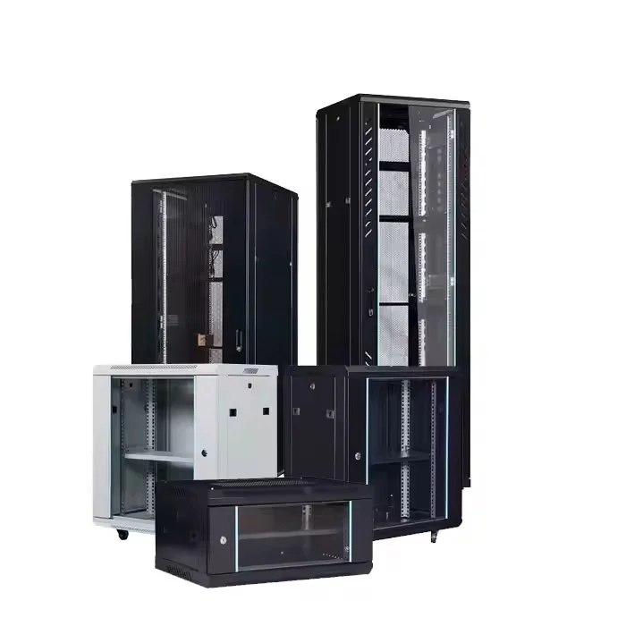
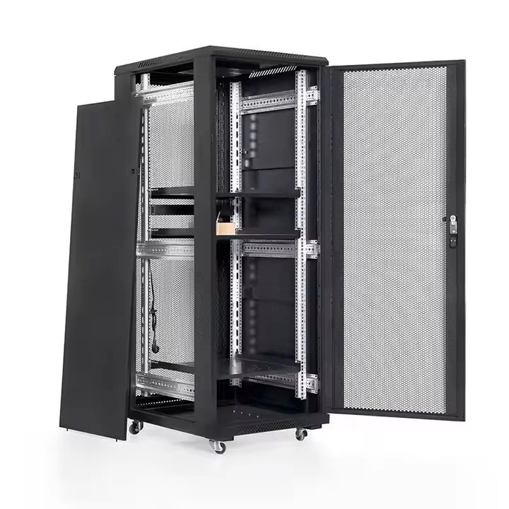
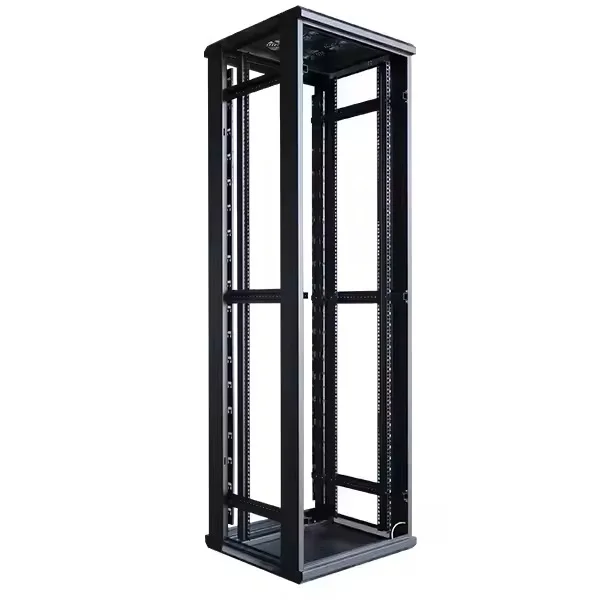
About Evergreen Machinery
If you have sheet metal fabrication projects, we can handle them for you. We can produce a wide range of products, including server racks, wall-mounted racks, enclosures, and more. Our production facilities and processes are fully equipped, covering every stage from material cutting, wire drawing, bending, welding, surface treatment, to final assembly.
If you have any needs or questions, you can contact us.