What Are Engineering Drawings?
Imagine a conference room in a factory: engineers from different countries, they may speak Chinese, English or Spanish, and when the same set of engineering drawings is unfolded, all of them point to the same defect location on the drawing – that’s an engineering drawing.
This visual language, composed of lines, symbols and numbers, can accurately describe the shape, size, material and more than 200 technical parameters of an object. According to statistics, 70% of the quality problems of modern industrial products originate from drawing errors, which shows its importance.
Historical Development
On the walls of the Luxor Temple in Egypt, archaeologists have found drawings of the building’s structure dating back 3,400 years, with column spacing labeled in hieroglyphics.
The standardized system of threads established by British engineer Joseph Whitworth during the Industrial Revolution is still the cornerstone of mechanical drawing.
By the 1980s, the popularity of some software, such as CAD (Computer Aided Design), made the leap from hand-drawing to three-dimensional modeling possible.
Why Engineering Drawings Are So Important
Just like the surface roughness symbol ▽ on the drawing, no matter which country’s machinist sees ▽0.8, they all know that they have to use fine grinding process to achieve the accuracy of Ra0.8μm. The value of engineering drawings is reflected in:
- Information carrier: carries 200+ manufacturing parameters such as materials, processes, tolerances, etc.
- Collaboration medium: allowing designers, engineers, and tradesmen to share a unified technical knowledge without an information gap.
- Legal evidence: When quality disputes arise, drawings are the key evidence for determining responsibility.
Anatomy of The Core Elements of An Engineering Drawing
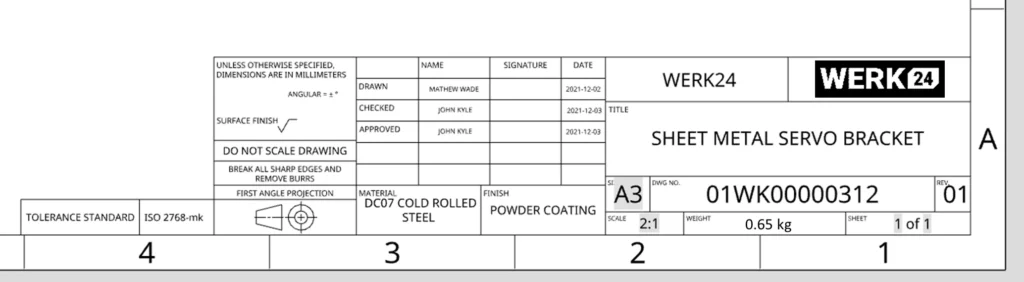
Title Bar and Frame Specification
The title bar is the label for the drawing and therefore must be included:
- Corporate information area: LOGO size must not be larger than 10 x 10mm (ISO standard)
- Change log area: each modification needs to be identified with a capital letter identifying the version (e.g. REV.B)
- Scale trap: 1:2 means that the graphic is reduced by half, but the size figures are still labeled as they are in the real world
Projective Methods and View Types
Orthographic Projection
Stand your cell phone on a table and shine a flashlight vertically – the shadow that appears on the screen is the orthographic projection. Engineering drawing uses this “vertical illumination” principle to break down a three-dimensional object into six orthographic views.
Interestingly, the German engineers used the analogy of a “glass box”: imagine that the object is enclosed in a transparent cube, and take a picture of each of the six sides is the basic view.

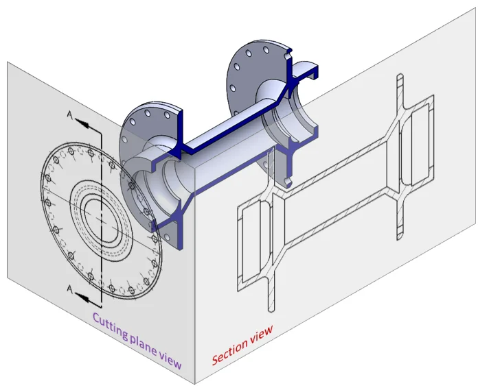
Cutaway View
When it comes to complex parts like automobile gearboxes, engineers will conduct an “autopsy” like a surgeon. A full-section view is like a CT scan, a half-section view preserves some of the exterior features, and a stepped-section view is like slicing through a cake in layers to show the inner core.
Detail Magnification Technology
When the details of a watch gear’s teeth are the size of a grain of rice in a conventional view, a partial magnification view acts like a microscope to label critical areas five times larger.
The auxiliary view, on the other hand, is like adjusting the camera angle to specifically capture the true shape of a slant or surface, avoiding the loss of aerodynamic efficiency due to projection distortion as in early airplane propeller drawings.
Dimensioning
Four Elements of Dimensioning
Pick up any mechanical drawing and you’ll find that dimensioning is like notes on a musical score:
- The dimension line is the horizontal line of the pentatonic scale, drawn with a 0.25mm fine solid line
- Dimensional boundaries are like nub lines, extending 2-3 mm from the measured contour.
- Arrows should be drawn as 1:3 acute
- Numbers always face up or to the left, 3.5mm font height is the common industry standard
The investigation of the 2017 Shinkansen gearbox accident in Japan revealed that a reverse labeled diameter symbol, Ø, led to a misreading of the bearing size by 0.5mm, which ultimately triggered system resonance. This warns us that labeling specification is the lifeline of engineering safety.
Selection of Baseline
On a BMW engine block drawing, you’ll see three datum boxes A|B|C, which aren’t drawn randomly:
- A datum must be the assembly contact surface; usually, the largest plane is selected.
- B-datum controls rotational degrees of freedom, with preference given to cylindrical surfaces.
- C datum to determine the orientation of the part, commonly used symmetry centerline
Just like building a house first foundation, size labeling must establish a stable benchmark system. German engineers have a mnemonic: “the main benchmark to determine the overall, auxiliary benchmark tube details.”
Tolerance Marking
When seeing Φ20±0.01, it means:
- Part pass size between 19.99-20.01mm
- 15% increase in machining cost for every 0.001mm increase in accuracy
Boeing has experimented: the aircraft rivet hole tolerance from ± 0.1mm tightened to ± 0.05mm, this move directly increased the manufacturing cost of 23%, but the airframe fatigue life increased by 40%, is also considered to be both good and bad.
The Pitfalls of Labelling
- Death Arrow: Arrow tail exceeds size boundary = size failure
- Black hole in numbers: Φ20 marked on non-circular view = machining must be wrong
- Datum drift: arbitrary change of measurement datum = assembly interference
- Tolerance superposition: chain labeling cumulative error up to ±0.5mm
In 2021, a company directly lost $8 million in orders due to uncontrolled accumulated tolerances of the robot arm, which caused the repetitive positioning accuracy to deteriorate from ±0.02mm to ±0.15mm.
Symbol System for Engineering Drawings
Surface Roughness
The number after the symbol ▽ represents the size of roughness:
- ▽0.2=Mirror polish (surgical tool grade)
- ▽1.6=Fine grinding (bearing mating surface)
- ▽12.5=rough milling (non-contact surface of casting)
Tesla motor rotor shaft is super-finished with ▽0.4, with nano-coating technology, making Model S Plaid achieve 2.1 seconds zero hundred acceleration. And the hydraulic rod of agricultural machinery only needs ▽3.2, and can reach the standard with sandpaper polishing.
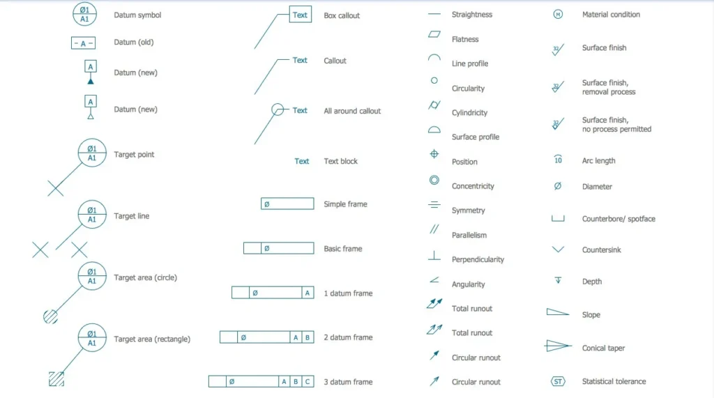
Form and Position Tolerance
This is indicated when seeing⏊ 0.02|A:
- Verticality requirement 0.02mm
- Measurement based on A datum
- Equivalent to a deviation of no more than the diameter of a hairline over a length of 200 mm.
Huawei’s 5G base station heatsinks use⌭ 0.05 flatness control to ensure uniform heat dissipation from tens of thousands of fins. The batch with uncontrolled precision had caused the base station to overheat and go down, resulting in a direct loss of 260 million orders.
Welding Symbols
The weld symbol is represented by a triangular flag:
- Solid triangles represent fillet welds
- The number 8 indicates that the height of the soldering foot is 8mm.
- Circle ○ stands for Surround Welding
The steel pipe piles for the Hong Kong-Zhuhai-Macao Bridge in China were beveled on both sides, with the symbol combination “▶◀ [5/8]” denoting a V-bevel with a depth of 5mm and eight welds. This symbol system allowed welders from China, Germany and Japan to work seamlessly together to create the miracle of the world’s longest cross-sea bridge.
Material Marking
When you see “SCM440” in the title bar:
- S=Steel
- C = Chromium
- M = molybdenum (Molybdenum)
- 440 = 0.40% carbon content
Japan’s Mitsubishi Heavy Industries turbine blades are labeled “INCONEL 718”, a nickel-based alloy that retains its strength at 900°C, but requires special tools for machining – that’s why the material column of the drawing has a direct impact on production costs.
Five Steps to Reading a Map from Scratch
The first step: quickly locate the key information
Senior engineers get the drawings first look at the lower right corner of the title bar, within 5 seconds to grasp the following core information:
- Material grade: Q235A (low carbon steel) and 304SS (stainless steel) processing process is vastly different
- Drawing version: REV.C stands for Third Revision, and it must be verified that the shop is using the latest version
- Special marking: the words “NDA – Non-Disclosure Agreement Drawings” imply that photographs are prohibited for distribution.
Case in point: In 2021, a drone manufacturer failed to meet electrical conductivity standards for 2,000 housing components because it did not recognize the “anodized” requirement in the title bar.
Step 2: View Disassembly
The main view is not chosen randomly; it must satisfy two golden laws:
- Feature maximization: show the most contour detail of the part
- Machining guidance: in the same direction as the machine’s clamping direction
For example, shaft parts must be selected axis horizontally placed view, easy to understand the lathe operator
Step 3: Dimensional Chain Tracing – Finding the Design Reference Points
The hidden logic chain of dimensioning:
Design datum (ideal position) → Process datum (machining positioning) → Measurement datum (quality control reference)
Practical skills: use a red marker pen to circle all the dimensions with a box (the theoretical correct size), these are the starting point for error calculation
Step 4: Special Symbols Deciphering
Form and position tolerances are the “penal code” of the drawing, for example:
- ⏊ 0.02 | A | B: flatness error shall not exceed 0.02mm, to the reference A, B for reference
- ◎ Φ0.05|C: Round runout tolerance band diameter 0.05mm, rotational detection around datum axis C
Step 5: The Correlation of Cross-page Drawings Reading Skills
Rules for reading complex equipment drawings:
- Related tags: Find “See Sheet3 partial enlargement B-B” class note
- Layer management: turn off the annotation layer in CAD software and focus on viewing solid contours
Dimensional closed-loop checking: the outline dimensions of the assembly drawing must be equal to the sum of the dimensional chains of the parts ± fit tolerance.
Top 5 Common Mistakes Made by Newbies
Disproportionate Drawings
- Disaster scene: a novice machines a 1:2 scale part as 1:1, causing a robot joint to jam
- Self-help solution: highlight title bar scale values with a red border, force preview of scale before printing
Omission of Key Dimensions
- CLASSICAL CASE: 2019 A foundry’s drawings were not labeled with a release slope, which prevented the finished product from being ejected
- Defense mechanism: create a dimensional checklist (must include locating dimensions/shaping dimensions/overall dimensions)
“Mirror parts” caused by projected chaos
- Industry event: An aircraft part was misread in the third angle projection, and the left and right parts were installed in reverse to trigger a system alarm.
- Ultimate defense: adding 3D axonometric drawings as “references” in the margins of the drawing.
Runaway Tolerance Stacking
- Problem: Cumulative overshooting of multiple chain dimensional tolerances
- Solution: Change to the datum marking method, mark the theoretically correct dimensions and control tolerances individually.
Vague Material Labeling
- Painful lesson: “stainless steel” does not distinguish between 304 and 316, offshore platform parts corrosion perforation in 3 months
- Standardized practice: must be marked with the full grade number (e.g. ASTM A276 Type304)
Summarize
Reading engineering drawings is the most basic skill of an engineer. If you can’t even read engineering drawings, various unpredictable situations will occur during the actual manufacturing of parts, causing huge losses.
If you can see from an A4 drawing the shape of the part, how it was machined and how many loose parts were assembled together, then you have reached a high level.