Forging Technology and Improvement of Passenger Car Crankshaft
The crank is the connecting part of the main journal and the connecting rod journal, and its section is elliptical. In order to balance the inertial force, there is a balance weight at the crank. The balance weight is used to balance the unbalanced centrifugal moment of the engine, and sometimes to balance a part of the reciprocating inertial force, so that the crankshaft rotates smoothly. The requirements for dynamic balance during crankshaft processing are very high, strict batch management is required for the production process, and extremely high requirements are placed on the consistency and dimensional stability of forgings in the same batch. Crankshaft process design and forging mold manufacturing have high requirements, and the control in the forging process also requires precise control.
Due to its complex shape, high safety requirements, and small machining allowance, the crankshaft of a car is the most difficult to forge. At present, there are few manufacturers with mass production capacity. With the upgrading of products, major OEMs have put into production energy-saving and environment-friendly engines one after another, pursuing high strength and lightweight for crankshafts. In particular, mass-automatic production lines for passenger car crankshafts have begun to popularize, and the requirements for forgings are also increasing; must choose Energy-saving and efficient forging processes can keep up with the development of OEMs.
We have accumulated some valuable experience in exploring the forging process of the 4-cylinder crankshaft of passenger cars in the manufacturing process for many years. The following focuses on the analysis and analysis of the forging process characteristics of the 1.5-liter 4-cylinder crankshaft of a certain type of car and some experience in the actual production process. Summarize.
Key Points of Forging Process Design for Typical Passenger Car Crankshaft
The forging of the 4-cylinder crankshaft (Fig. 1) of a typical car adopts the process of horizontal split die forging. Edge, shaping→cooling in temperature-controlled cooling line (or quenching and tempering heat treatment)→shot peening→flaw detection→cleaning→packaging.
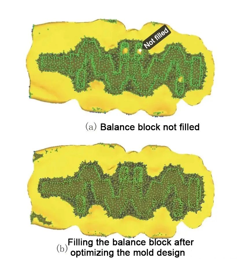
According to the function and process characteristics of the crankshaft, the crankshaft is a typical long-shaft forging, the balance weight part is narrow and deep, and the draft angle is small (generally 1°~1.5°), so the balance weight part is difficult to form, according to the forging process manual In the normal process, the flattening, pre-forging and final forging are designed and simulated. A suitable round bar is selected, and the balance block is not filled, as shown in Figure 2(a). It is necessary to optimize the pre-forging and final forging dies. After a series of optimizations, the simulation results can be filled as shown in Figure 2(b).
I won’t go into details about the conventional design criteria here, but focus on summarizing several optimizations and improvements:
1. In order to improve the filling problem of the balance weight, the tongue part (splitting platform) in the middle of the balance weight of the pre-forging mold is lowered by 10-15 mm, and the convex fillet of the edge mold is increased to R8-R10mm.
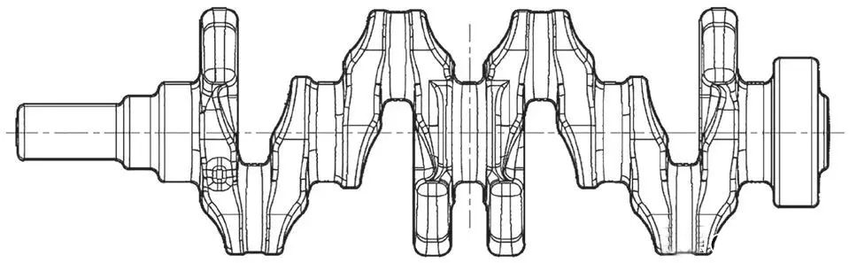
Figure 1 Passenger car 1.5-liter four-cylinder crankshaft
2. The flash around the counterweight of the pre-forging die and the final forging die is optimized, and a resistance wall is added. The shape and position are set according to the shape of the forging.
3. The height of the mold flash bridge around the balance weight of the final forging die is about 1mm higher than in other positions.
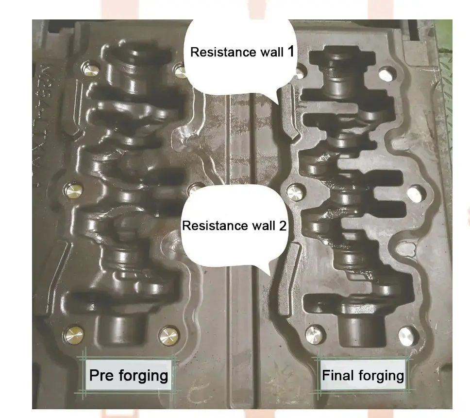
Figure 3 Crankshaft pre-forging and final forging dies
After the above improvements, in the actual production of the 4000-ton hot die forging press, the balance block is well filled, the pass rate is greater than 99%, and the die life is 6000-7000 pieces.
4. Since the crankshaft is a long-shaft forging, the cavity of the balance weight is deep and thin, and the draft angle is small, in order to eject reliably and stably and reduce ejection deformation, it is necessary to design 6 to 8 ejector pins (originally 4 ejector pin), which is especially important in the automation line, the mold structure is shown in Figure 4.
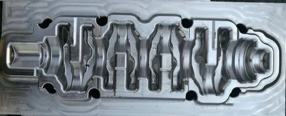
Figure 4 Forging die structure of a certain type of crankshaft press for passenger cars
Through the application of simulation software, combined with actual work experience, simulating the forging process can optimize the mold structure design, greatly shorten the mold development cycle, and improve the first-time success rate of development.
Important improvement direction and control points of high-end passenger car crankshaft forging process
High-end passenger car crankshaft forgings have complex shapes, less machining allowance, basically no machining of balance weights, etc., and have high safety requirements. To meet the requirements of processing on a fully automatic machining production line, the requirements for forgings and the difficulty of quality control are greatly increased. If the size of the blank is out of tolerance and the dynamic balance is out of tolerance, the first process of the automatic machining line will alarm and the material will be thrown away, and even cause the shutdown of the line in serious cases. In addition to excellent process design, forgings for this requirement also require skilled forging operation skills and high-level process control guarantees. The following is a summary of some improvement experience and process control points in the actual production process:
Taking the crankshaft of a certain car in Figure 5 as an example, the shape of the forging is complex, and the side machining allowance of the four balance weights marked “1” is only 1.5mm, and the four balance weights marked “2” are non-processed. Moreover, the thickness of the balance block marked with “2” is only 8mm, deformation is very easy to occur during the forging process, and the maximum error modulus is allowed to be 0.5mm. During the forging process, the mold is slightly loose, or the forging is jammed, or bumped, the clamping force is too large, or the forging is deformed, which will cause unqualified.
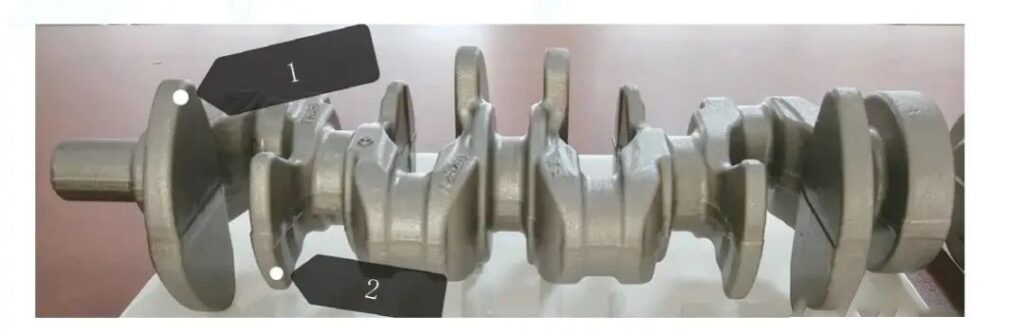
Figure 5 The crankshaft forging of a certain car
This is the most difficult forging piece we have encountered so far. After nearly a year of exploration and improvement, it has reached a stable mass production state. The quality of the forging, especially the dynamic balance performance and appearance quality, has reached or even exceeded that of the original European factory. level. There are mainly the following aspects of experience:
⑴. On the basis of successfully solving the problem of the fullness of the balance weight, in order to solve the problem of trimming and deformation of the balance weight, the local flash around the balance weight is thinned. The thickness of the flash here is 2.5mm, and the rest is 4.5mm.
⑵. The wrong modulus of forgings is 0.5mm, which is difficult to control, resulting in a frequent adjustment of the mold during the production process, and it needs to be adjusted more than 4 times in each shift. , and the addition of four-corner locks has successfully controlled the occurrence of wrong molds, and achieved stable production in each shift, and basically, no adjustments are required on shifts.
⑶. In order to completely remove the scale and improve the surface quality of the forging, the billet is descaled twice, and the scale is removed by high-pressure water after induction heating and high-pressure air before pre-forging.
⑷. In order to control the deformation of the mold and the deformation during trimming, the material and processing accuracy of the forging die and the trimming die is tackled. By optimizing the clearance of the trimming die and improving the material, the cutting-edge life of the trimming die can be extended Up to 20,000 pieces remain sharp. And the life of the forging die and trimming die is controlled separately, and the replacement time is determined according to the life, so as to avoid the service life of the die.
⑸. The crankshaft forging process is fully automated, and temperature control is carried out for each step in the forging process, from intermediate frequency heating → billet making (roll forging or extrusion) → forging → upper control cold line → lower control cold line for temperature monitoring and control. Enter the MEMS system. The abnormal parts are automatically put into the abnormal product basket and the quantity is counted, and the above important parameters are monitored synchronously on the on-site visual Kanban so that the operation status of the production line is clear at a glance.
⑹. In addition to the three-coordinate inspection of the first forging piece, design and manufacture special inspection tools for straightness and error, and 100% rapid inspection of forgings in the forging process.
Other Concerns in the Design of the Crankshaft Forging Process
⑴. During the crankshaft forging process, the form of the flash of the crankshaft forging die and the design of the blocking groove, the machining accuracy of the mold, the proficiency of the forging operation, and the lubrication method are all important and indispensable.
⑵. Forging misalignment control. Crankshaft forgings have high requirements for errors, and the forging process is prone to fluctuations. The overall forging die can be designed and the forging die lock can be added, and automatic detection can be adopted to strengthen process control.
⑶. The optimization of pre-forging shape design can improve many defects of forgings, which is the key to the success of forging process design and should be paid attention to. In order to make the material flow smoothly during pre-forging, the middle connection of the balance weight should be made as a transition between a straight line and a large arc as much as possible in the pre-forging design, so as to increase the volume of this part, which is conducive to the flow of metal materials and the filling of this part for final forging. The treatment of the pre-forged small head cavity is also worth noting. The length of the small head is increased by about 10mm, and the draft angle at the end of the small head is made to be beveled at about 45°. This can avoid folding of the small end during final forging, and at the same time, making a bevel at the end of the small end is conducive to blowing off the oxide skin on the lower die, so as to avoid the accumulation of oxide skin at this place and cause the small end of the forging to be short of material.
⑷. Grasp the forging temperature. Attention must be paid to the forging temperature range. In general, try to forge at the upper limit temperature, and the minimum forging temperature is not lower than 1100 ℃. Forging temperature has a great influence on forming, especially in the early stage of development and trial production, unskilled operation and poor connection of actions such as spraying release agent, resulting in long intervals between forging steps and temperature drop, resulting in insufficient actual final forging temperature, which affects forming. However, for non-quenched and tempered steel, the forging temperature should not be too high. It is necessary to ensure that the material properties meet the grain size requirements. This requires tracking and monitoring in the actual process to determine the ideal forging temperature range.
⑸.Computer forming process simulation. In order to successfully develop the crankshaft forging process, necessary analysis methods should be equipped. Try to use DEFORM, QFORM and other forging simulation software for simulation, and combine the practical experience of the forging process to optimize the design in time. Computer applications provide powerful analysis methods for process design. Enterprises need to be Equipped with specialized personnel for simulation analysis. Unconditional enterprises can adopt the joint method of enterprises and universities or research institutes
Like this page? Share it with your friends!