
Approximate Superplastic Technology
The research on the superplasticity of the microcrystalline material structure (the average size of the grains usually does not exceed 10 ~ 20μm) is at elevated temperatures and relatively low deformation speed (usually 10-4 ~ 10-3s-1) ongoing. In fact, it has been determined that any polycrystalline material, including industrial alloys such as aluminum-based, titanium-based, and nickel-based, can be transformed into a superplastic state. In many cases, the use of superplasticity in metal pressure processing can ensure lower deformation forces, reduce the number of process steps, and improve the mechanical properties and dimensional accuracy of semi-finished products. Under conventional forging conditions, the forging temperature range of these metal materials is relatively narrow, especially when rolling thin plates, high ribs, and thin-walled parts, the heat of the billet is quickly absorbed by the tool, and the temperature drops rapidly. Not only does it need to greatly increase the tonnage of the equipment, but it is also easy to cause cracking of the tooling. Especially titanium alloy is more obvious, it is very sensitive to deformation temperature, when the deformation temperature drops from 920 ℃ to 820 ℃, the deformation resistance almost doubles. The superplastic deformation force of titanium alloy is only about 1/30 ~ 1/10 of ordinary rolling.
Titanium alloys are widely used in many industrial fields, including aerospace, automotive, and biomedicine. As we all know, many titanium alloys have low plasticity and uneven structure in the supply state. Therefore, it is of urgent practical significance to obtain inexpensive, high-quality, complex parts from these materials. One of the effective ways to solve this problem is to use superplastic technology. Unfortunately, producing ultrafine grains in various alloys is difficult and expensive.
Coarse-grained superplasticity
O.I.Вyly а, Р.L.Вlekvell (Strаthсlyde, Glаsgow University of Strath Clyde, UK), Р.А.Васин (School of Mechanical Engineering, State University of Mali, Russia), MKSаrаndzhi (Indian Technology School of Education and Research) collaborated on the study of coarse-grained superplasticity.
One of the main advantages of superplastic press forming is that the material can achieve very large deformations. However, many processes do not require deformation of 100% to 200%. Generally, the metal forging ratio reaches 5, that is, the deformation reaches 75%. Optimum is not always required in order to ensure the high serviceability of parts. Moreover, the coarse lamellar microstructure has better stability against fatigue crack propagation.
In order to obtain high-quality blanks, rough-grained material blanks are first used, whose microstructure cannot guarantee the typical superplastic grain boundary slip deformation mechanism. Under this condition, since the sensitivity to deformation rate is lower than the material superplastic condition, the material can be deformed and softened, and the microstructure can be transformed during deformation. Experimental studies have pointed out that this process can be called approximate superplastic deformation, and some parts of the grain are broken, which can reach a relatively high deformation of 100% to 300%. Coarse-grained titanium alloys are used in the hot die forging of automobile wheel hubs. Two-phase (α+β) titanium alloys with flaky (Widmandelsteiner) microstructure have initial broken grains. β-phase about 250 μkm, α-phase flakes The average length is about 21 μkm and the thickness is about 2 μkm. This example simulates the process and analyzes the obtained results, demonstrating the feasibility of approximate superplasticity techniques.
Coarse-grained superplastic forging titanium alloy automobile wheel forming process simulation, as shown in Figure 14, for simplicity, all process simulations use isothermal (T=900℃), the contact surface has the same friction coefficient of 0.5, and the assumption of using glass lubricant.
Coarse-grained superplastic forming steps for high-end automobile wheel hubs
Figure 15 Simulation of the first step – original ingot upsetting
The final forging simulation results are shown in Figure 15. In the figure, there is obviously a dead zone after the first deformation process, as shown by the letter А, the grain changes little after upsetting. At the same time, there is a В region in the blank, this part of the material will form a rim in the subsequent deformation, and the grain size will change from 80μkm to 40 ~ 50μkm. The plastic deformation here is about 50%.
Deformation results of coarse-grained blanks for TC4 rims
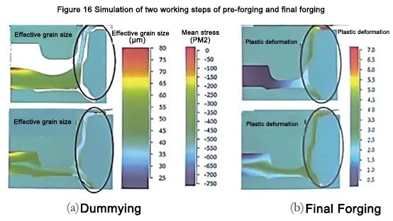
From the standpoint of rim deformation, 3 -step die forging is still feasible (Fig. 16). It is not difficult to see that at the end of the third step, the cumulative plastic deformation of this part is 300% to 400%, in some places it exceeds 450%, and in some points, it even exceeds 500%. Although the deformation results showed that the microstructure uniformly changed to 30 to 35 μkm at the end of the second step and to 20 to 25 μkm at the end of the third step, the tensile elongation of the specimen with such a microstructure unexpectedly reached δ=400 %~500%. The subject simulation can show that in all severe deformation areas of the forging, the average stress of the forging is negative (under the condition of hydrostatic compression), that is to say, the crack source or pores are eliminated, and the performance is extremely high.
Low-temperature superplasticity
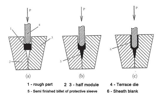
Modern aircraft engine fans and compressor blades are partly made of carbon fiber. Due to the reduced weight under the condition of ensuring structural strength and reliability, it is highly competitive with titanium alloy blades. However, the biggest weakness of carbon fiber blades is that the impact toughness is too low. In the process of use, the leading edge is hit by sand, gravel, and birds, which will cause major accidents of aircraft crashes and death. To solve this thorny problem, the leading edge of the blade is covered with a high-strength titanium alloy protective cover by means of fixing parts or glue. But the manufacture of titanium alloy boots is a very complex subject because the boots have different cross-sections, including thin walls and reinforced, heavy leading edge cross-sections. In addition, the sheath has complex spatial shapes, including curved shapes in the horizontal direction and vertical plane curvatures.
The American Nonferrous Gas Turbine Corporation (Chromаlloy Gаs Turbine Corporation USА ) designed and used the titanium alloy Ti-6Аl-4V three-dimensional blank to manufacture the sheath. The blank is milled to create an internal V-shaped pocket. The sidewalls are then extruded in a die before final machining. The extrusion temperature is 850 ~ 900 ℃, and the surface gas is saturated without protective gas. The wall thickness of the part is only 0.2 to 0.5mm, and manufacturing it requires very difficult machining.
On November 27, 2018, the “2018 (11th) International Automotive Technology Annual Conference and ‘Automotive Technology Innovation Award Award Ceremony” was grandly held in Shanghai. 2018 (11th) International Automotive Technology Annual Conference focuses on new energy vehicles, energy management, autonomous driving, intelligent networking, and lightweight and other industry hotspots, aiming to carry out professional technical exchanges and build a cutting-edge technology sharing platform. The “Automotive Technology Innovation Award” awards ceremony aims to recognize the creators and promoters of advanced technologies in the automotive and parts industry. Speech experts, domestic and foreign auto OEMs and auto parts suppliers, representatives of university research institutes, representatives of associations and government agencies, and media representatives conducted in-depth professional and technical exchanges with more than 400 guests, and jointly looked forward to a better future for travel.
Bending should be done after coextrusion (Figure 18).
Process steps in different stages of compound extrusion
In order to verify the feasibility of the proposed composite extrusion process, a digital simulation method was used. The simulation process was established using the software Deform 3D, and the model was established using the basic assumptions:
– the original blank is divided into 98000 finite elements;
– the mold as a rigid body;
——The movement speed of the punch is 0.5mm/min;
——The friction between the blank and the mold is set to Coulomb friction, μ=0.2;
——Metal flow under isothermal conditions, blank temperature = 650 ℃;
– The anisotropy or even recrystallization of the blank is not considered during the forming process.
Figure 18 Sketch of bending steps
The initial size of the blank: is 5mm × 10mm × 270mm. It is confirmed that the blank material adopts the titanium alloy Ti-6Аl-4V with rheological characteristics collected from this database.
Figure 19 shows the state of the blank when it is deformed in the mold and the corresponding stage-forming images.
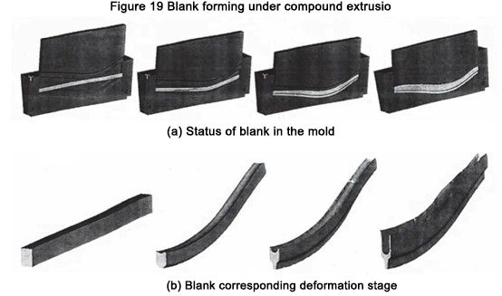
Figure 19 Blank forming under compound extrusion
The simulation results show that the proposed process is feasible, the wall is formed uniformly, and the logarithmic deformation degree at the wall reaches e ≈ 3. The recommended process is effective at temperatures not exceeding 700°C, which reduces the cost of manufacturing mold parts.
We know that titanium alloys including TC4 (Ti-6Аl-4V) in the ultrafine grain state affect the low-temperature superplasticity effect. The preparation of the ultra-fine grain structure of the blank includes the use of a bar with a diameter of φ70mm, changing the axial load, upsetting several times under the condition of gradually reducing the temperature, and then rolling at 600 °C to a thickness of 5mm. The degree of logarithmic deformation e ≈ 3. Deformation results The average grain size is 0.5 μm (Figure 20).
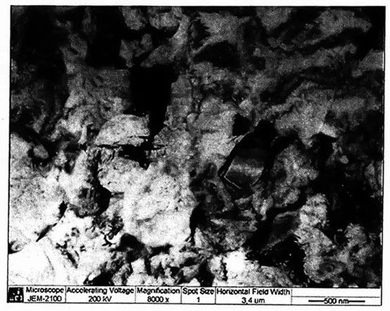
Figure 20 Microstructure of the blank
The proposed titanium alloy temperature is 650 ~ 950 ℃, and the pressure processing process adopts the following material label coating: apply FR-6 glass lubricant to the original blank 1. These coatings protect against oxidation and gas saturation and even achieve the intended mechanical properties of machining in argon. Therefore, it is recommended to apply a coating as a lubricating material in the extrusion process where the blank is in contact with the die.
The shape of the sheath has curves in the horizontal plane and bends in the vertical plane, and needs to be straightened in the corresponding planes before extrusion. Under the condition of a given horizontal plane, the blank is laid in the two halves of the die for extrusion. Close the die halves to shape the blank to the desired shape and use a U-shaped punch for forward and reverse extrusion. Then, change the mold to realize the bending step with a V-shaped punch.
All forming processes are completed on a CNC isothermal forging hydraulic press, and its main technical parameters are: the nominal force of 25MN, with a pressure of 680kN, completed at 650°C, and a deformation speed of 0.5mm/min. The mold material is tool steel 5Cr3W3MoVSi, and the mold is shown in Figure 21.
After compound extrusion, the forgings meet the drawing requirements. There are no folding and sandwich defects in appearance. During the simulation, no wall distortion was observed. The machined part is shown in Figure 22.
The original structure of the blank is severely deformed (e ≈ 3), which makes it have an ultra-fine grain structure and reduces the process temperature. The microstructure of the sample cut from the wall and front of the sheath is shown in Figure 23. The average grain size of the forgings was determined to be 0.3-0.5μm by a semi-transparent electron microscope. The grain size was reduced to 0.3 μm, and the metal of the wall was severely plastically deformed under the condition of back extrusion. The energy is stored and the grain size is reduced so that the strength of the material is increased by 20% to 30%, and various performance indicators meet the actual requirements. The simulation and test results prove that the trial mass production of sheath parts can be implemented.
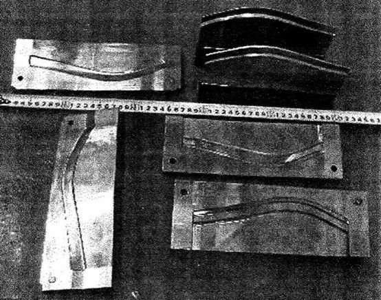
Figure 21 Compound extrusion and bending die
Figure 22 Side and Bottom of Sheath
Figure 23 Microstructure of jacket sample
Like this page? Share it with your friends!
