

At present, the most cutting-edge technologies in the world forging industry mainly include plate forging technology, semi-isothermal forging technology, and approximate superplastic technology. These new technologies are developed to meet the needs of today’s industrial development. Their outstanding advantages are more energy saving, consumption reduction, and environmental protection. Cost-effective, so the speed of development should not be underestimated. Next, we will share the development of these new technologies with you, in order to achieve the effect of attracting jade.
mandrel-type parts with spherical flanges from sheet metal
The aerospace industry’s requirements for high-quality parts and their use are increasing year by year. Using the latest plate forging technology, a new process can be used to design mandrel-shaped parts with spherical flanges (Figure 3). In other industrial sectors such as automobiles, robots, tools and instruments, instrumentation industries, etc., mandrel-type parts with spherical flanges can be seen as the main spherical hinge shafts, and even the outer planetary wheels on cars can be manufactured by plate forging.
Plate Forging Technology
Technical advantages
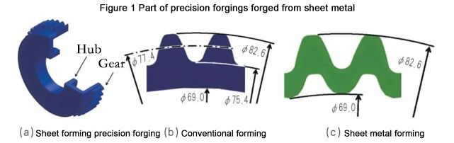
The so-called plate forging technology, as the name implies, is the forging deformation of the plate into a precision forging, as shown in Figure 1. The earlier researcher of this technology was Professor Wang Zhigang of Gifu University in Japan. He pointed out that the main advantages of plate forging are:
(1)The optimal technology for energy saving and consumption reduction can reduce costs by 45% on average, save materials by 15%, and improve production efficiency by 30%.
(2)Plate forging technology can form parts with the same precision as machining.
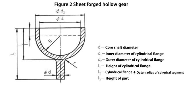
(3)Complex parts such as gears, outer planetary wheels, and hubs can be formed. In terms of weight reduction, hollow gears can be easily made by using plate forging technology, as shown in Figure 2.
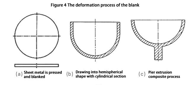
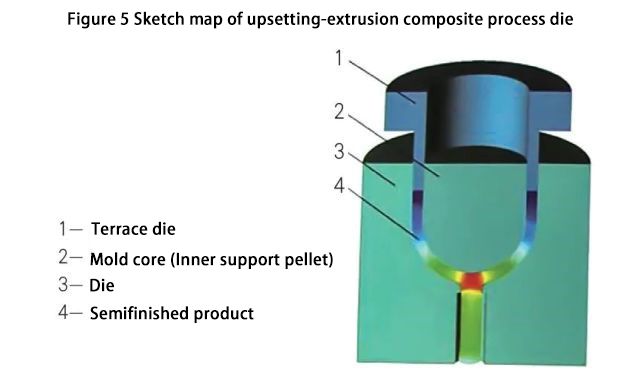
The plate forging process of parts with spherical flanges is drawn up as shown in Figure 4. After the slab is cleaned, blanking (Figure 4a) → deep drawing into a hemisphere with a cylindrical section (Figure 4b) → upsetting and extruding the wall. The schematic diagram of the mold structure is shown in Figure 5.
Using this process technology, a 45# steel plate with a thickness of 2.5mm was forged. After forging, the inspection showed that the working surface roughness of the die was 7-9, the surface roughness of the forgings was 8-9, and the diameter accuracy was 3-5. level, see Figure 6 for actual objects.
Semi-isothermal forging technology
Isothermal die forging means that the blank and die are formed by die forging at an almost constant temperature. In order to ensure the conditions of constant temperature forming, the die must also be heated to the same temperature as the blank and kept warm, so it is called isothermal die forging; isothermal die forging deformation rate Generally in (10-3 ~ 10-2)/s.
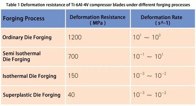
Isothermal die forging is often used in the precision forming of difficult-to-deform materials such as titanium alloys, aluminum alloys, and magnesium alloys in the aviation and aerospace industries. In recent years, it has also been used in the precision forming of non-ferrous metals in the automotive industry and machinery industries. This is because the process of closed hot die forging under isothermal conditions has a series of advantages: it can improve the structure of the deformed material, thereby improving its mechanical properties; obtain a small or no margin, no flash, and the shape has a minimum die forging slope ( 0 ~ 1°) forgings; obtain deep cavities with no inclination (1° ~ 3°) or no inclination; material utilization rate is increased from 50% ~ 70% to 80% ~ 95%; increase the unimaginable surface rate to 60% to 90%; due to the low deformation resistance, the deformation force is reduced to 1/4 to 1/3 (sometimes to 1/6 to 1/5); the subsequent machining amount is reduced by more than 30% to 60%; Improved working conditions. The deformation force of isothermal die forging of titanium alloy is only about 1/8 to 1/5 of ordinary die forging, see Table 1.
Development Trend of Isothermal Die Forging
Since the isothermal die forging process is completed on a hydraulic press, its relative deformation speed is not large and the productivity is not high. It is possible for aerospace forgings to be used in small batches, with high requirements, regardless of cost. However, it is unacceptable for such a slow deformation speed for automobile parts with a large amount of consumption. The optimal isothermal deformation speed should consider the maximum speed. The increased die load at this speed does not exceed the allowable load to ensure normal forging production. The degree of heating deformation of the blank does not exceed the allowable value, and there is no discomfort in the structure and properties of the blank material. Change, using a semi-isothermal die forging process.
Some maximum deformation speeds are determined in the simplified scheme, and the deformation speed can be increased in individual stages without harming the working performance of the die and the quality of the die forgings, and can also increase the productivity of the process. For example, it is entirely possible to speed up when the mold is not yet in contact with the blank. In the mass production of parts, some secondary conditions are blurred, and the pursuit of product quality, performance, cost, and productivity is in a new relative balance.
Semi-isothermal die forging technology of aluminum alloy bearing cap
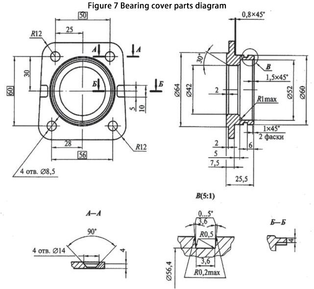
The bearing cover parts are shown in Figure 7. It is installed on the high-pressure fuel pump of the automobile and bears the static load from the bearing, and also ensures the sealing performance of the connection. This part caused an accident due to leakage caused by the use of castings. Analysis of the structure of the part shows that it has a relatively complex shape and should be manufactured by semi-isothermal die forging multi-step method on a mechanical press.
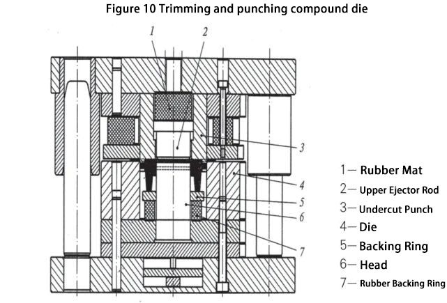
The deformation process of the blank adopts two procedures. The die-forging process of the part is divided into three steps: pre-forging, final forging, trimming, and punching, as shown in Figure 8. Placing two die forging stations on one die set (Fig. 9) minimizes the operating time between the two stations and avoids repeated heating. A mechanical ejector rod and an automatic moving forging walking beam are arranged in the die to ensure that the forgings are ejected from the die bores of the first and second stations and move in an orderly manner. A guide post guide mechanism is set at each die forging station to ensure the precision of the die forgings. Figure 10 shows the composite die for trimming and punching after the part is deformed.

In the die forging process, the emphasis should be on the heating and heat preservation of the die. The working parts of the mold are always heated with gas and kept at 250 ℃ ~ 300 ℃. The die forging equipment does not use a hydraulic press but uses the company’s existing 1,000 – ton hot die forging press to form a semi-automatic semi-isothermal forging production line.
Impeller semi-isothermal forging technology – local heating
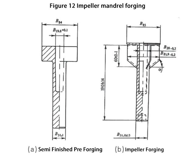
Figure 12 shows the impeller mandrel pre-forging (a) and forging (b), and Figure 13 shows the semi-isothermal extrusion die for the part with the impeller mandrel. The forgings are made of 7075 super-hard aluminum alloy and heated to t=450 ℃. Since one end of the mandrel is provided with a flange composed of blades, in this case, in order to make the difficult-to-fill blades fill the corner of the die, an intermediate frequency induction heater is installed in the positive extrusion part of the die with the flange so that The condition of forming the blade blank is close to isothermal (t=350 ℃ ~ 450 ℃ ), and the heater only heats the blade flange part of the blank, which saves the heating of the entire die, so the blade in the flange part of the forging obtains a good filling effect.
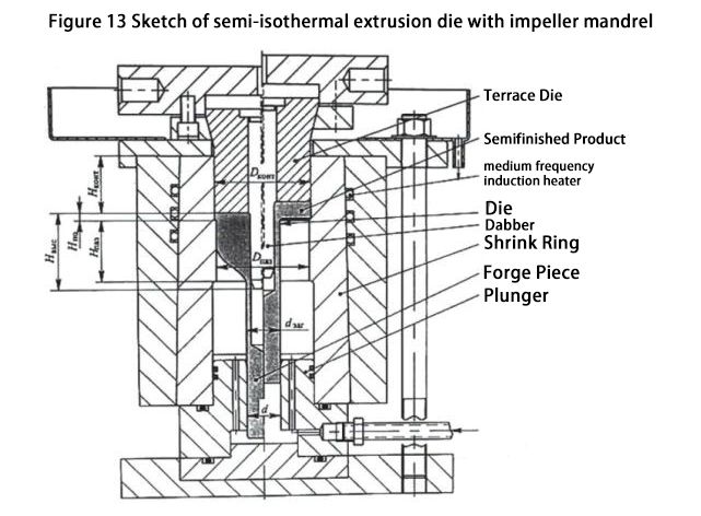
In the die, the rod and center of the forging are located in the center hole of the piston, and the center hole of the piston is d > dзаг. Even if the diameter of the blank reaches a positive tolerance, there is still a gap with the hole wall. The slider of the press completes the working stroke, and the punch drives the mandrel to squeeze into the depth of the semi-finished blank. At the moment when the end of the punch comes into contact with the end face of the flange of the semi-finished product, an annular gap is formed between the die opening of the female die and the mandrel, and the metal is squeezed into the annular groove to form the mandrel. In order to ensure the stability of the above-mentioned mandrel during the extrusion process, a corresponding deep pre-formed hole Hg (blank pre-forging hole depth ) <Lk (blank final forging hole depth ) should be designed for the die forging blank. The drop between the diameter DКОНТ ( outer diameter of punch ) and Dпаз (outer diameter of concave die) ensures good filling of the groove of the concave die, which is exactly the length required for positive extrusion formed by the contact between the blank metal and the side surface of the groove of the concave die.
allowable thickness tolerance Hh is obtained at the moment when the stroke of the slider of the press and the movement of the punch is terminated, which is not greater than 0.1d of the inner diameter of the punch. When the punch returns to its original position (upper), the lubrication system sprays lubricating and cooling cavity liquid. Hydraulic oil enters the cavity to eject the forging, and the surface of the rib should be carefully removed from the die to prevent the ejection from being deformed. Lubricant-coolant flushed from the die is drained from groove 9, leaving only a thin layer of lubricant on the surface of the die cavity. Further machining and dynamic balancing are done after the forgings are obtained.
Like this page? Share it with your friends!
