1. Fatigue damage of welded structures
A large amount of statistical data shows that more than 80% of the failures of engineering structures are caused by fatigue. According to a research report submitted to the U.S. Congress by the National Bureau of Standards of the U.S. Department of Commerce, the United States pays $119 billion every year for fractures and prevention of fractures, which is equivalent to 4% of the total national economic output. Statistics show that the vast majority of fractures are caused by fatigue. Caused by.
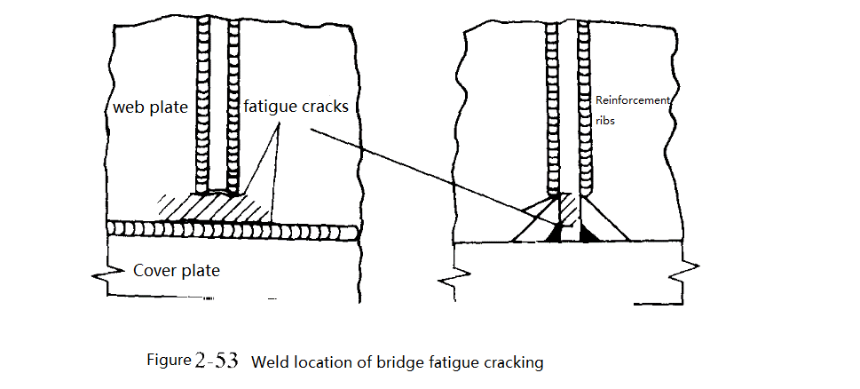
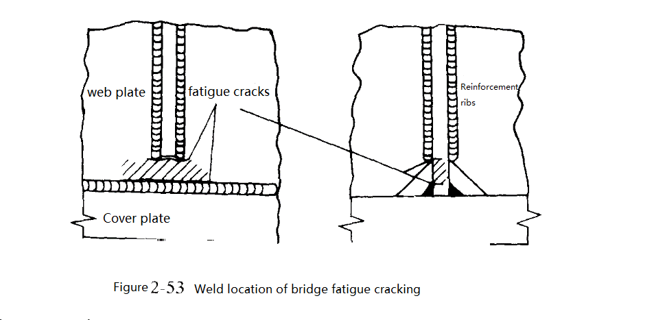
The weld toe is near the end of the weld, as shown in Figure 2-53. There is a high-stress concentration in the cracked part shown in the figure. Under the action of load, the plane displacement of the web is concentrated on a relatively narrow and unsupported web height, that is, the height of the web from the flange to the bottom of the stiffener (hatched area), causing the web to crack.
Fatigue is defined as the initiation and slow propagation of cracks caused by repeated stress, resulting in damage to structural components. The fatigue fracture process usually goes through three stages: crack initiation, stable expansion, and unstable expansion.
1) Characteristics of fatigue fracture
When performing macroscopic analysis of fatigue fractures, the fractures are generally divided into three zones, corresponding to the stages of fatigue crack formation, expansion, and instantaneous fracture. They are called fatigue source area, fatigue expansion area, and instantaneous expansion, respectively. The area is shown in Figures 2-54.
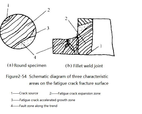
The fatigue source zone is the real record left on the fracture surface by the formation process of fatigue cracks. Since the fatigue source area is generally very small, it is difficult to distinguish the cross-sectional characteristics of the fatigue source area at a macroscopic level. Fatigue sources generally always occur on the surface, but defects inside the component, such as brittle inclusions, etc., can also occur inside the component. Sometimes, there is more than one fatigue source, but there are two or even more than two. For low-cycle fatigue, the strain amplitude is large, and there are often several fatigue sources located at different positions on the fracture surface.
The fatigue crack growth zone is the most important characteristic area on the fatigue fracture surface. Its macroscopic morphological characteristics often appear as shell-like or beach-corrugated stripes, and the stripe advancement lines generally advance from the crack source to the surroundings, are arc-shaped lines, and are perpendicular to the expansion direction of fatigue cracks. Its microscopic characteristics are fatigue cracks, also known as fatigue striations, and there are tens of thousands of them in each shell pattern. It is usually a regular pattern of parallel stripes alternating between light and dark. Generally, each stripe represents a load cycle. The spacing of fatigue stripes is between 0.1-0.4Уm. Generally speaking, the fatigue stripes of face-centered cubic metals ( such as aluminum, aluminum alloys, and stainless steel) are relatively clear and obvious. The fatigue stripes of body-centered cubic metal and metal with close-packed hexagonal structure are far less obvious than the former. For example, the fatigue stripes of steel are short and discontinuous, and the outline is not obvious.
In addition, from a macro perspective, some components, especially thin plates, do not have obvious shell-like patterns on their fracture surfaces, but there are obvious fatigue steps. In an independent fatigue zone, two fatigue sources expand forward and meet to form a fatigue step. Therefore, the fatigue step is also a feature of the fatigue crack growth zone.
The instantaneous fracture zone (or final fracture zone) is the rapid fracture that occurs after the fatigue crack expands to a critical size. Its characteristics are the same as the rapidly damaged radial zone and shear lip in the static load tensile fracture, but sometimes only the shear lip appears without the radial zone. For very brittle materials, this zone is a crystalline brittle fracture.
2) Factors affecting the fatigue strength of welded structures
Factors that affect the fatigue strength of the base metal (such as stress concentration, cross-sectional size, surface condition, loading conditions, etc.) also have an impact on the welded structure. In addition, some characteristics of the welded structure itself, such as changes in the performance of the joint near the seam area, welding residual stress, etc., may also have an impact on welding fatigue.
(1) Effect of stress concentration: In welded structures, there are different stress concentrations at the joints, which have varying degrees of adverse effects on the fatigue strength of the joints.
(2) The influence of changes in metal properties in the near-seam area. Experimental research shows that welding of low carbon steel under common linear energy. The fatigue strength of the heat-affected zone and the base metal are quite close, and changes in the mechanical properties of the metal near the seam zone have little impact on the fatigue strength of the joint.
(3) Effect of residual stress: The effect of residual stress on the fatigue strength of the structure depends on the distribution state of residual stress. In areas with high working stress, such as stress concentration points and the outer edge of bending components, the residual stress is tensile, which reduces the fatigue strength; conversely, if compressive residual stress exists there, the fatigue strength is increased. In addition, the impact of residual stress on fatigue strength is also related to factors such as the degree of stress concentration and the number of stress cycles. In particular, the higher the stress concentration coefficient, the more significant the impact of residual stress.
(4) Effect of defects: The effect of welding defects on fatigue strength is related to the type, size, direction, and location of the defects. Flake defects (such as cracks, lack of fusion, lack of penetration) have a greater impact than defects with rounded corners (such as pores); surface defects have a greater impact than internal defects; defects located in stress concentration areas have a greater impact than those in a uniform stress field. Defects have a greater impact; flaky defects perpendicular to the force direction have a greater impact than in other directions; defects located in the residual tensile stress field have a greater impact than in the residual compressive stress area.
3) Measures to improve fatigue strength
(1) Reduce stress concentration in components
Stress concentration in the structure is the most important factor in reducing the fatigue strength of welded structures. The following measures are generally taken.
① Use reasonable component structural forms to reduce stress concentration to improve fatigue strength.
② Reasonably select the joint form. Try to use butt joints with a small stress concentration coefficient and a gentle transition in weld shape. It is more advantageous to use continuous welds than intermittent welds for vibration loads, and fillet welds should be used as little as possible.
③ When using fillet welds, comprehensive measures must be taken, such as machining the ends of the welds, rationally selecting the shape of the fillet plates, and ensuring penetration of the root of the fillet welds.
④ Use surface machining to eliminate various grooves in and around the weld to reduce the stress concentration of the joint.
(2) Process measures to improve the fatigue strength of welded structures
① Welding specifications should be correctly selected in terms of the process to ensure that the weld is well-formed and has no internal or external defects.
② TIG welding arc shaping can greatly improve the fatigue strength of welded joints.
③ Adjust residual stress. There are two types of methods: overall treatment of the structure and components, including overall annealing or overload pre-stretching; local treatment of the joint, that is, heating, rolling, local explosion, and other methods are used at a certain part of the joint to concentrate stress on the joint. Residual stress occurs.
④ Improve the mechanical properties of the material. Surface strengthening treatment, squeezing with a small wheel, tapping the weld surface and transition zone with a hammer, or spraying the weld zone with a small steel shot can improve the fatigue strength of the joint.
(3) Use special protective measures
The use of special plastic coatings to improve the fatigue performance of welded joints is a new technology, and its effect is significant.
2. Brittle fracture of welded structures
Since welded structures have been widely used, brittle fracture accidents of welded structures have occurred in many countries, and the consequences have been serious and even catastrophic. The results of a joint investigation by the British Atomic Energy Agency and the United Nations Technical Committee show that most of the catastrophic accidents that occurred in 12,700 pressure vessels under manufacturing were brittle fractures, with an accident rate of 2.3×10~4; among 100,300 pressure vessels in service, The catastrophic accident rate is 0.7×10~4, and the damaging accident rate is 12.5×10~4, totaling 13.2×1O~4. Among many serious accidents, the most typical example was the collapse of the Hesselt Bridge on the Albert Canal in Belgium on March 14, 1938.
1) Characteristics of brittle fracture
(1) Brittle fracture generally occurs when the stress is lower than the structural design stress. There is no significant plastic deformation, and it extends to the entire structure, causing serious losses.
(2) Brittle fracture often starts from stress concentration points, such as defects in components and welds.
(3) At low temperatures, thick sections and high strain rates, under dynamic loads, can easily cause brittle fractures. Research on many brittle fracture accidents shows that there are many reasons for welding brittle fracture, but the main ones are improper selection of materials, unreasonable design, imperfect manufacturing process, and inspection technology.
2) Factors affecting brittle fracture of metals
(1) Effect of temperature on damage mode
Lowering the temperature will change the failure mode from plastic failure to brittle failure. This is because as the temperature decreases, the risk of cleavage fracture increases, and the material will transition from ductile to brittle fracture; that is, the brittle transition temperature of the material increases.
(2) Influence of stress state
an object is subjected to the external load, different everyday stress б and shear stress т are generated on different sections, among which there is a maximum everyday stress бmax and a maximum shear stress тmax. бmax and тmax and their ratio бmax/тmax are related to the loading method. a=бmax/тmax is called the stress state coefficient, which is related to the loading method and the shape of the part. The increased stress state of б is conducive to ductile fracture due to plastic deformation shear stress, while the reduction of б is conducive to brittle fracture due to normal stress.
(3) Impact of loading speed
Research shows that increasing the loading speed can promote brittle failure of the material, which is equivalent to lowering the temperature. It should also be pointed out that at the same loading rate when there are defects in the structure, the strain rate can have a doubled adverse effect. Because the stress is concentrated at this time, the local plasticity of the material is greatly reduced.
(4) Influence of material state
① Influence of plate thickness: First of all, thick plates are prone to form a plane strain state of three-dimensional stress at defects. In addition, thick plates are rolled less often, have a loose structure, and have uneven internal and external properties.
② The influence of grain size. The grain size has a great influence on the brittle transition temperature. The finer the grains, the lower the transition temperature.
③ Influence of chemical composition. Elements such as C, N, O, H, S, and P in steel will increase its brittleness.